
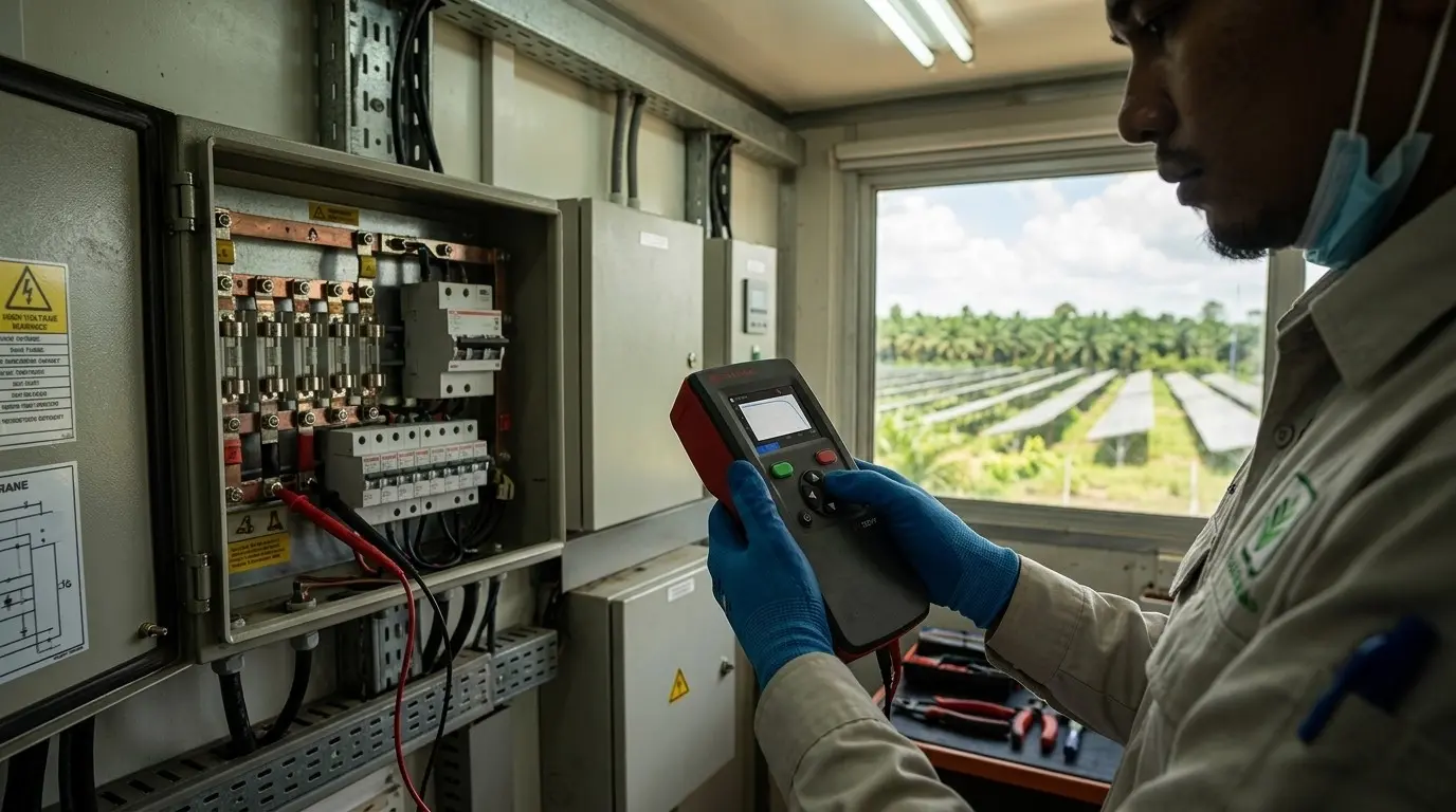
Commissioning Tests: What Has to Be Measured Before Energisation?
Published by Quinn Lai | By InverPower Technical Team
Published 22 August 2026 · Last updated 22 August 2026
DIRECT ANSWER
IEC 62446-1 sets the sequence: continuity of protective earthing and bonding, polarity, string open-circuit voltage, string current, functional checks and insulation resistance of the DC circuits — all recorded on a test certificate with the array's documentation. It is the evidence that the installation was safe on the day it was handed over.
Commissioning is where an installation stops being a construction site and becomes an asset with a warranty behind it. The tests are not difficult and they are not slow. What makes them valuable is that they are measured, recorded and dated, which is exactly what nobody can reconstruct two years later when a question arises.
The sequence, in order
Continuity first: the protective earthing and equipotential bonding conductors, verified with a low-resistance ohmmeter rather than a continuity beep. Then polarity, at every string, before anything is connected to the inverter — a reversed string is easy to make and expensive to energise. Then open-circuit voltage per string, compared against the design figure and against sibling strings; then string current, either short-circuit or operational, again compared string to string.
Insulation resistance of the DC circuits comes next, at the test voltage the standard sets for the system voltage, with the results compared against the minimum acceptable value. Functional tests finish the sequence: switchgear operates, the inverter starts and stops as intended, and the interface protection behaves as configured.
Do it in daylight and record the conditions. Voltage and current readings move with irradiance and module temperature, so a set of measurements taken across a whole afternoon without noting conditions cannot be compared with anything, including itself. Note irradiance and temperature at the start and end of the session, and take sibling strings back to back.
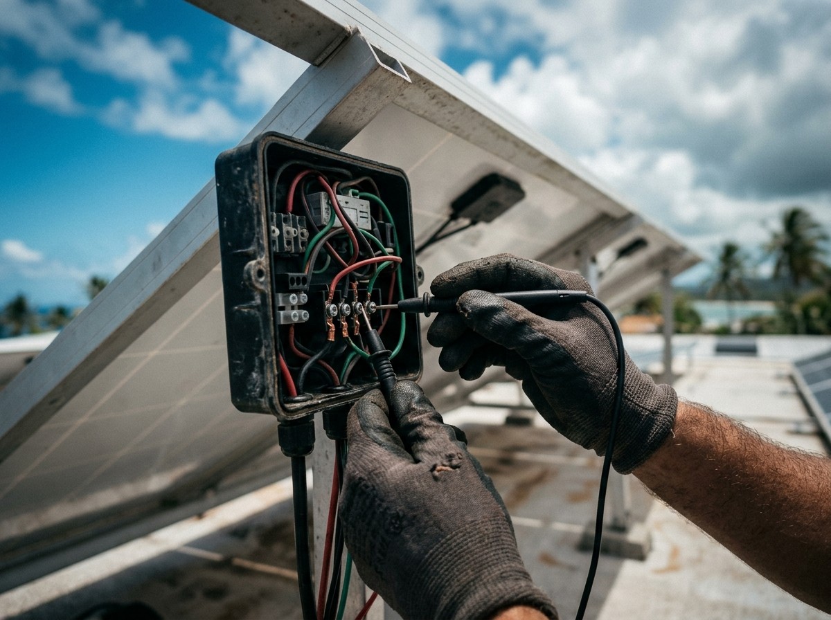
Comparison is what makes the numbers useful
A single string's voltage tells you little on its own, because irradiance and temperature move it. The same reading against three identical strings measured within the hour tells you a great deal. That is why the test record should list strings side by side with the conditions noted, and why the commissioning engineer should be looking for the odd one out rather than for a pass mark.
This is also the reason to keep the record. When a string reads low in year three, the commissioning figures are the only baseline anyone has. Without them the discussion becomes an argument about whether it was ever right.
The instrument matters
A general-purpose multimeter is not built for this. A PV commissioning instrument is rated for the DC voltages an array produces, measures open-circuit voltage and current safely on a live string, performs insulation resistance testing with the array in circuit, and time-stamps and stores results so the certificate is generated from measurements rather than transcribed by hand.
The safety rating is the part worth insisting on. Test equipment used on a 1000 V or 1500 V array has to carry an appropriate category rating for the circuits being worked on, along with leads and probes rated to match. Using an instrument outside its rating is the kind of decision that looks economical until the day it does not.
The record that goes with it
| Test | What it proves | What gets recorded |
|---|---|---|
| Protective earthing continuity | The bonded structure is connected | Measured resistance per position |
| Polarity | Strings are the right way round | Confirmed per string |
| Open-circuit voltage | Strings match the design and each other | Value per string, with conditions |
| String current | No string is underperforming at handover | Value per string, with conditions |
| Insulation resistance | No leakage path to earth | Value per circuit and test voltage |
| Functional tests | Switchgear and inverter behave as designed | Pass, with settings recorded |
| Interface protection | Grid protection matches approved settings | Settings and witness record |
Commissioning testing and O&M testing are different jobs
Commissioning is a one-time verification against the design. O&M testing is periodic verification against the commissioning baseline, and it uses a wider set of tools: insulation resistance again, string measurements again, plus infrared thermography to find hot joints and failing diodes, and IV curve tracing where a string's shape has changed rather than just its magnitude.
Cadence should follow the site rather than a calendar rule. A coastal industrial roof with heavy soiling and salt air justifies more frequent checks than a sheltered inland installation, and any site with a performance guarantee behind it should be tested often enough to catch a problem inside the reporting period rather than after it.
Thermography deserves its own slot in the programme. It finds the faults that produce no fault code at all — a warm connector, a diode conducting when it should not, a joint that has loosened under thermal cycling — and it does it while the system is running, which means no downtime for the customer. It has to be done under load and in good irradiance to show anything, so it is a mid-morning job rather than a convenient one.
Sourcing the equipment
Seaward test instruments for commissioning and periodic verification, and Beny protection and safety devices for the DC and AC sides of the installation, both held in Malaysia alongside the inverters, cable and connectors. Tell us the array voltage, the system size and whether the instrument is for one-off commissioning or an O&M programme, and we will tell you which model suits and what is in stock.
One last point that costs nothing: the competent person signing the installation off under the Electricity Supply Act 1990 is signing off what was measured. Give them measurements worth signing.
Frequently Asked Questions
What tests are mandatory before energisation?
The commissioning sequence in IEC 62446-1 — protective earthing continuity, polarity, string open-circuit voltage, string current, insulation resistance and functional tests — recorded on a test certificate. The distribution licensee's own interface protection requirements apply on top of that.
How often should O&M testing happen?
Set it by exposure rather than by a fixed rule. Annual verification is a reasonable baseline; coastal, industrial and heavily soiled sites justify more often, and any site with a performance guarantee should be checked frequently enough to catch a fault inside the reporting period.
Can a standard multimeter be used for commissioning?
Not for the full sequence. Insulation resistance testing needs an instrument that applies the correct test voltage, and measuring a live array needs equipment and leads rated for its DC voltage and fault energy. A commissioning instrument also stores time-stamped results, which is what turns readings into a record.
What is the point of measuring insulation resistance?
It finds a leakage path to earth — damaged insulation, water in a connector, a pinched cable — before the system is energised. It is also the test that most often catches installation damage, because a cable crushed under a rail measures differently from an intact one.
Sources
- IEC — IEC 62446-1, Photovoltaic (PV) systems: requirements for testing, documentation and maintenance, including the commissioning test sequence — https://webstore.iec.ch
- IEC — IEC 62446-3, outdoor infrared thermography of photovoltaic modules and plants — https://webstore.iec.ch
- IEC — IEC 60364-6, Low-voltage electrical installations: verification — https://webstore.iec.ch
- Seaward — solar test instrument documentation and application notes — https://www.seaward.com
- Electricity Supply Act 1990 (Act 447) and the Electricity Regulations 1994 — competent person duties at commissioning — https://lom.agc.gov.my
About InverPower
InverPower is Malaysia's A–Z solar component distributor — Sungrow Preferred Distributor and Sunkean Sole Distributor — supplying EPCCs, installers, and government projects nationwide.
Explore the InverPower resource hub at inverpower.com.my
Related InverPower posts:
- Grounding and Bonding for Solar Arrays: How Do You Prove Continuity?
- TNB Grid Code for Solar: What Must EPCCs Do Before Energization?
- Why Do Solar Projects Get Rejected at TNB Interconnection Review?